MIL-PRF-1/1661C
Ltr
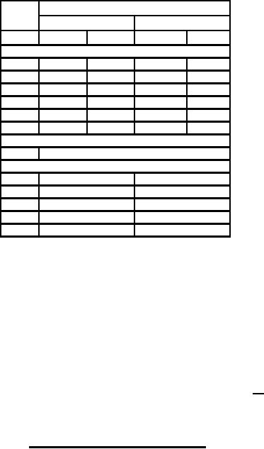
Dimensions
Inches
Millimeters
Min
Max
Min
Max
Conformance inspection, part 2
A
----
1.630
----
41.40
B
1.315
1.435
33.40
36.45
C
4.270
4.770
108.46
121.16
D
.355
.365
9.02
9.27
M
.077
.083
1.96
2.11
N
.188
----
4.78
----
Conformance inspection, part 3 (see note 4)
H
Base: A4-102 (EIA)
Reference dimensions
E
1.000
25.40
F
1.969
50.01
G
1.062
26.97
J
.500
12.70
K
.375
9.53
NOTES:
1. Types 8765 and 8370, use anode connector A.
2. To replace type 5957, remove anode connector A.
3. To replace type 5956, remove anode connector A and replace with anode connector B.
4. Dimensions shall be checked during the initial production and once each succeeding 12-calendar
months in which there is production. An accept on zero defect sampling plan shall be used, with sample
of three tubes with an acceptance number of zero defects. In the event of failure, the test will be made as
a part of conformance inspection, part 2, with an acceptance level of 6.5 (see 11/ on page 3). The
regular "12-calendar month" sampling plan shall be reinstated after three consecutive samples have been
accepted.
FIGURE 1. Outline drawing of electron tube type 8765 - Continued.
Custodians:
Preparing activity:
Army - CR
DLA - CC
Navy - EC
Air Force - 11
(Project 5960-3696)
DLA - CC
Review activities:
Army - CR4, MI
Navy - AS, CG, OS
Air Force - 99
5