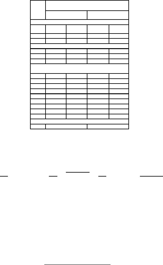
MIL-PRF-1/1658C
Dimensions (see note b)
Ltr
Millimeters
Inches
Conformance inspection, part 1
Min
Max
Min
Max
A
428.63
479.43
16.875
18.875
B
----
142.88
----
5.625
Conformance inspection, part 2
D
304.80
330.20
12.000
13.000
E
214.12
217.42
8.430
8.560
G
96.60
97.10
3.803
3.823
Conformance inspection, part 3 (see note i)
(see notes c, e, f, g, and h)
C
----
76.20
----
3.000
F
----
160.32
----
6.312
J
95.25
146.05
3.750
5.750
L
111.13
117.48
4.375
4.625
M
----
285.75
----
11.250
N
15.24
16.51
0.600
0.650
P
25.40
50.80
1.000
2.000
Q
22.23
47.63
0.875
1.875
R
7.85
8.00
0.309
0.315
Nominal dimensions (see note a)
H
3.18
0.125
NOTES:
1. Dimensions without tolerances are for information only and are not required for inspection purposes.
2. Metric equivalents (to the nearest 0.01 mm) are given for general information only and are based upon 1 inch = 25.4 mm.
3. Anode terminal shall be No. 10-32 UNC-2A roundhead machine screw 3/8 inch (9.53 mm) long with washer. The anode terminal
extension may be removed for shipment.
4. Leads shall be flexible. Lead connections shall be suitably identified. Lead connections, lead identification, lead insulation, and
lead insulation sleeving shall be inspected under periodic check and shall be as follows:
Lead insulation
Lead
Color
Type
Sleeving Color
H (heater)
Yellow
HA-1
Yellow
G (grid)
Yellow or Green
HA-1
Green
R (reservoir)
Red
HA-1
Red
5. Lead terminal shall be in accordance with figure 2.
6. Insulation sleeving shall be as specified in MIL-I-3190.
7. Dimensions C and F define extent of rigid portion of tube below mounting flange. Clearance for this part of tube shall be provided
in equipment.
8. Holes R shall be inspected for orientation by using the base gage outlined on figure 3.
9. These dimensions shall be checked during the initial production and once each succeeding 12-calendar months in which there is
production. An accept on zero defect sampling plan shall be used, with a sample of three tubes with an acceptance number of
zero. In the event of failure, the dimension checks shall be made a part of conformance inspection, part 2, code level D, with an
acceptance level of 6.5 (see note 10). The regular "12-calendar months" sampling plan shall be reinstated after three consecutive
samples have been accepted.
10. This specification sheet uses accept on zero defect sampling plan, in accordance with MIL-PRF-1, table III.
FIGURE 1. Outline drawing of electron tube type 8789 - Continued.
8
For Parts Inquires call Parts Hangar, Inc (727) 493-0744
© Copyright 2015 Integrated Publishing, Inc.
A Service Disabled Veteran Owned Small Business