MIL-PRF-1/1648C(NAVY)
TABLE I. Testing and inspection - Continued.
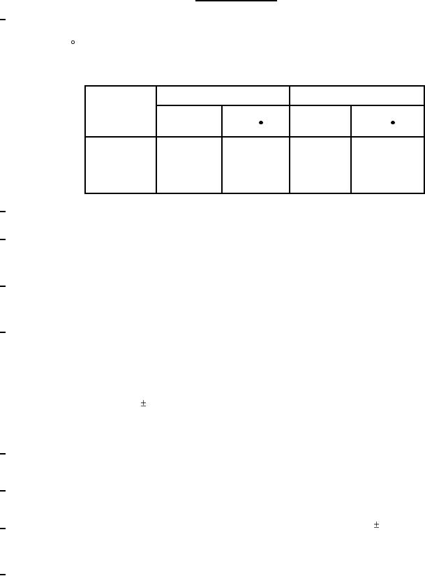
1/ In all cases of operation, force-air cooling is required and the maximum temperature ratings should not be exceeded. An air-system
socket, such as the EIMAC SK-800 series, and air director (chimney) SK-806, or equivalents, shall be used. The cooling table is
based on operation of the tube in an SK-800B socket with SK-806 chimney, with air flowing in a base-to-anode direction, with
cooling air at 50 C maximum, and for operation at frequencies below 30 MHz. Additional air cooling may be required at higher
frequencies. Airflow must be applied before or simultaneously with electrode voltages (including the heater), and may be removed
simultaneously with them. When long life and consistent performance are factors, cooling in excess of minimum requirements is
normally beneficial.
Anode
Sea level
10,000 feet
dissipation
Airflow
Approx press
Airflow
Approx press
(cfm)
(cfm)
drop (In H20)
drop (In H20)
500 W
7.5
0.04
11
0.06
1,000
17.5
0.23
24
0.21
1,500
34
0.60
45
0.80
2/ In all electrical tests involving application of heater voltage, the use of an air-system socket and chimney is allowable, and forced-air
cooling is permitted in order to maintain temperatures within the allowable maximum.
3/ This test shall be the first performed after the holding period. The tube shall be connected as an ion gauge, with the specified
potentials applied, and the highest initial reading shall be taken as the test value. Ion current is read with a microammeter in series
with the negative anode lead. Except for Ef, all voltages shall be applied simultaneously, with an automatic current regulator
controlling Ic2 to the value specified.
4/ This test shall be performed yearly. A regular double sampling plan shall be used, with the first sample of three tubes with an
acceptance number of zero, and a second sample of three tubes with a combined acceptance number of one. In the event of
failure, the test will be made as a part of conformance inspection, part 2, acceptance level of 6.5, inspection level S3. The regular
yearly double sampling plan may be reinstated after three consecutive samples have been accepted.
5/ Each tube under test (TUT) shall be subjected to one sweep cycle in each of the three axes, X, Y, and Z. One sweep (28 to 500 Hz,
ascending only) shall be covered in 6 to 15 minutes. The specified voltages shall be applied during the test, using the basic circuit
shown on figure 3. Tubes found to electrically oscillate for causes other than vibration shall not be tested nor rejected on this test.
Each tube shall be vibrated for 60 seconds at the frequency which gives the maximum vibration (noise) output voltage in each of the
three axes. If at the end of the 60 seconds, the vibration output voltage is increasing, the vibration shall be continued until there is
no further increase. The tubes shall not show noise voltage output in excess of the maximum limit specified, except one intermittent
short shall be allowable during this test. In addition to reading noise voltage on the specified VTVM, or equivalent, a permanent
recording shall be made using a good quality recorder to produce a plot of noise voltage versus frequency. Noise voltage amplifiers
used with the recorder shall have a 1 dB frequency response over the range to be measured and the overall recording equipment
shall be capable of fast response in order to show sharp noise voltage spikes resulting from internal tube resonances or other
phenomenon. Prominent noise peaks indicated on the recording shall be individually investigated by fixed-frequency operation, and
the 60-second operation shall be made at the frequency of highest noise as so selected.
6/ Each TUT shall be subjected to the specified acceleration in the X, Y, and Z axes, with three shocks in each axis. Tubes showing
any permanent shorts, or more than one temporary short during the test, shall be rejected. The applied shock shall be an
approximate half-sine wave motion with the duration measured at the zero-axis level.
7/ When the stability test is performed, the same sample of tubes shall be used for the stability test and the linear amplifier power
output and IM distortion test, with the stability test performed first. The same test circuit shall be used for both tests. The absolute
value of the 3rd IM shall never be greater than the absolute value of the 5th IM.
8/ The life test shall be considered as destructive. All voltage and current meters shall be calibrated for 2 percent accuracy or better
as installed in the equipment. The circuit used need not be identical to that used for the linear amplifier power output and IM
distortion test. Prior to the performance of the life test, the tubes used shall have met the requirements of the linear amplifier power
output and IM distortion test.
9/ The test circuit of figure 1 shall be used. The input voltage shall be varied to obtain the average inverse voltage and the resistor R
shall be varied to obtain and maintain the forward power for the specified time. All unused tube elements shall be grounded. The
wattmeter shall be capable of reading over the range from dc to at least 600 Hz. Loading of the transformer is permissible.
4