MIL-PRF-1/1624B(NAVY)
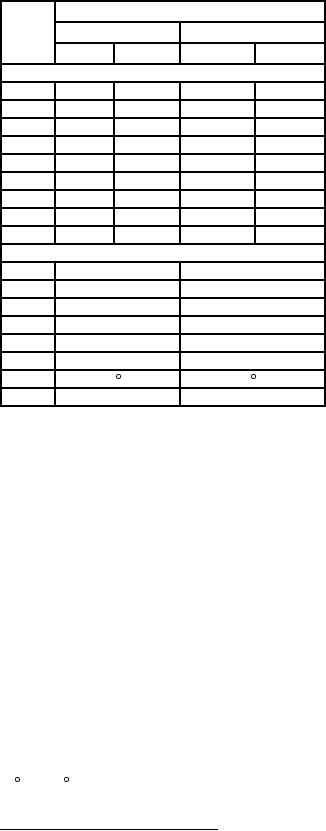
Dimensions
Ltr
Inches
Millimeters
Min
Max
Min
Max
Conformance inspection, part 2
G
.490
.510
12.45
12.95
T
3.180
3.194
80.77
81.13
Y
---
.060 RAD
---
1.52 RAD
AW
.900
.910
22.86
23.11
AX
.731
.739
18.57
18.77
AZ
.046
.054
1.17
1.37
BF
.151
.161
3.84
4.09
BG
.182
.192
4.62
4.88
BH
.153
.159
3.89
4.04
Reference dimensions
K
2.285
58.04
L
.235
5.97
M
.250
6.35
N
1.500
38.10
P
2.500
63.50
S
4.106
104.29
V
.060 x 45 chamfer
1.52 x 45 chamfer
Z
1.907
48.44
NOTES:
1. Reference plane "A" is defined as a plane passing along the face of the mounting plate.
2. Reference plane "B" is defined as a plane perpendicular to plane "A: passing through the axis of the holes, as shown at
reference plane "A".
3. Reference plane "C" is defined as a plane mutually perpendicular to planes "A" and "B" passing through the axis of the holes,
as shown at reference plane "A".
4. Includes angular as well as lateral deviations.
5. These diameters shall be concentric within 0.002 T.I.R.
6. Anode temperature shall be measured at this point.
7. For vibration and shock testing, the planes of testing shall be reference planes "A", "B", and "C".
8. This dimension applies to diameter "XX".
9. This diameter shall be concentric with diameter "XX" within 0.030 inch.
10. Heater terminal and cathode terminal shall be concentric within 0.010 inch.
11. Input connection mates with Jettron Products, Inc. connectors, No. 90-006 and 90-030, or equivalent.
12. Four (112) - 40 NC 3 holes spaced 120 , 30'/119 , 30' apart, by 0.250 inch deep.
FIGURE 1. Outline drawing of electron tube type 8682 - Continued.
9
For Parts Inquires call Parts Hangar, Inc (727) 493-0744
© Copyright 2015 Integrated Publishing, Inc.
A Service Disabled Veteran Owned Small Business