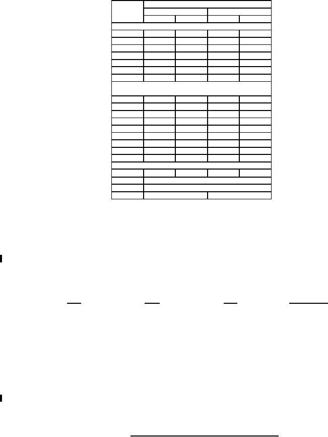
MIL-PRF-1/1361H
Dimensions
Ltr
Inches
Millimeters
Min
Max
Min
Max
Conformance inspection, part 2
A
8.000
10.500
203.20
266.70
B
---
5.625
---
142.88
D
9.500
10.500
241.30
266.70
E
5.938
6.063
150.83
154.00
F
5.324
5.364
135.23
136.25
U
---
2.500
---
63.50
V
---
1.500
---
38.10
Conformance inspection, part 3
(see note 10)
C
---
3.000
---
76.20
G
.307
.323
7.80
8.20
J
3.750
5.750
95.25
146.05
K
---
.500
---
12.70
L
4.375
4.625
111.13
117.48
M
---
.375
---
9.53
N
.875
1.875
22.23
47.63
P
1.000
2.000
25.40
50.80
X
---
4.563
---
115.90
Reference dimensions
89°30'
90°30'
89°30'
90°30'
H
R
5,000 CM (see notes 3, 4, and 5)
S
10,000 CM (see notes 3, 4, 5, and 6)
T
.125
3.18
NOTES:
1. Anode terminal shall be .25-20UNC-2A roundhead machine screw .50 inch (12.7 mm) long with washer .250 inch (6.35
mm) clearance diameter and .50 inch (12.7 mm) outside diameter.
2. Grid terminal shall be 6-32UNC-2A roundhead machine screw .50 inch (12.7 mm) long with washer, .188 inch (4.77 mm)
inside diameter and .375 inch (9.53 mm) outside diameter, and with 6-32UNC-2B hex nut.
3. Lead terminals shall be in accordance with figure 2.
4. Insulation sleeving shall be as specified in MIL-I-3190.
5. Leads shall be flexible. Dimensions S and R define cross sectional area of lead conductors. Lead connections shall be
suitably identified. Lead connections, lead identification, lead insulation, and lead insulation sleeving shall be inspected
under qualification and shall be as follows:
Lead insulation
Lead
Color
Type
Sleeving color
H (heater)
Yellow
HA-1
Other than black
HR (heater-reservoir)
Yellow
HA-1
Black
R (reservoir)
Red
HA-1
Other than black
6. Heater leads, 2 mounting holes as applicable, and grid terminals shall be aligned within ± 10°.
7. Dimension C and X defines extent of rigid portion of tube below mounting flange. Clearance for this part of tube shall be
provided in equipment.
8. Holes G shall be inspected for orientation by using the base gauge outlined on figure 3.
9. The optimum reservoir voltage shall be inscribed permanently on the top surface of mounting flange, as shown.
10. Dimensions shall be checked during the initial production and once each succeeding 12-calendar months in which there is
production. An accept on zero defect sampling plan shall be used, with sample of three tubes with an acceptance level of
zero defects. In the event of failure, the test will be made as a part of conformance inspection, part 2, with an acceptance
level of 6.5. The regular "12-calendar month" sampling plan shall be reinstated after three consecutive samples have been
accepted.
11. Dimensions are in accordance with ASME Y14.5M.
FIGURES 1 AND 1A. Outline drawing of electron tube types 7390 and 7390A - Continued.
8
For Parts Inquires call Parts Hangar, Inc (727) 493-0744
© Copyright 2015 Integrated Publishing, Inc.
A Service Disabled Veteran Owned Small Business