MIL-PRF-1/1329A
Dimensions
Ltr
Inches
Millimeters
Min
Max
Min
Max
A
---
1.640
---
41.66
B
.635
.645
16.13
16.38
C
---
.360
---
9.14
D
.790
.850
20.07
21.59
E
---
2.500
---
63.50
F
---
.225
---
5.71
G
---
1.450
---
36.83
H
1.213
1.223
30.81
31.06
J
---
2.265
---
57.53
K
---
.200
---
5.08
L
1.275
1.285
32.39
32.64
M
---
1.475
---
37.47
N
.207
.217
5.26
5.51
P
.6825
.6925
17.34
17.58
Q
---
1.843
---
46.81
R
.797
.807
20.24
20.50
S
.245
.255
6.22
6.48
T
.035
.045
.89
1.14
U
.065
.075
1.65
1.91
V
.70
.80
17.8
20.3
W
---
1.093
---
27.76
X
---
2.406
---
61.11
Y
---
.650 DIA
---
16.51 DIA
NOTES:
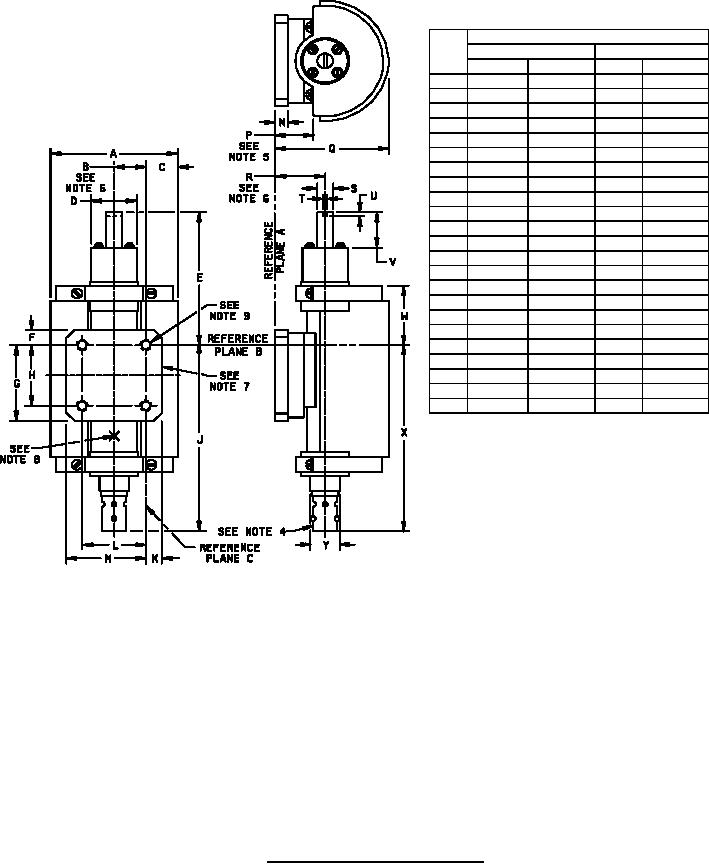
1. Reference plane "A" is defined as a plane along the face of the wave guide flange.
2. Reference plane "B" is defined as a plane perpendicular to plane "A" passing through the center of the holes as shown.
3. Reference plane "C" is defined as a plane perpendicular to planes "A" and "B" passing through the center of the
holes as shown.
4. AN-UG 290A/U BNC panel jack.
5. Includes angular as well as lateral deviation.
6. Parts on this centerline may vary from true location by .125 inch (3.17 mm).
7. To be coupled to an AN-UG-40A/U standard choke flange coupling.
8. Measure anode temperature at this point.
9. Pitch diameter to accept #8-32NC 60 GA only minor diameter of thread .140 inch (3.56 mm) (max).
FIGURE 1. Outline drawing of electron tube type 7521.
6
For Parts Inquires call Parts Hangar, Inc (727) 493-0744
© Copyright 2015 Integrated Publishing, Inc.
A Service Disabled Veteran Owned Small Business