MIL-PRF-1/1222D
Dimensions
Ltr
Inches
Millimeters
Min
Max
Min
Max
Conformance inspection, part 2
A
19.250
20.000
488.90
508.00
B
11.813
12.187
300.05
309.55
C
1.313 DIA
1.437 DIA
33.35 DIA
36.50 DIA
D
5.000
---
127.00
---
E
10.313
10.687
261.95
271.45
F
8.937
9.312
227.00
236.52
G
3.063 DIA
3.187 DIA
77.80 DIA
80.98 DIA
H
1.625
2.125
41.25
53.98
Conformance inspection, part 3
(periodic check)
R
BASE: B8-65 (EIA)
S
Bulb contact: C1-5
Reference dimensions (see note 5)
J
4.125
104.78
K
50°
M
20.000 R
508.00 R
N
1.000 R
25.40 R
P
7.687 R
195.25 R
NOTES:
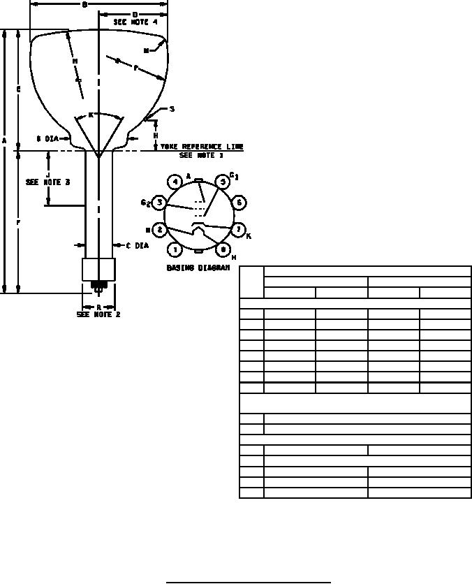
1. Reference line is determined by the plane of the upper edge of the reference line gauge
(JEDEC No. 112) when the gauge is resting on the cone.
2. Anode terminal aligns with pin No. 5 ± 10 degrees.
3. Recommended position for center of focusing field.
4. Useful screen radius.
5. Reference dimensions are for information only and are not required for inspection purposes.
FIGURE 1. Outline drawing of electron tube type 12DP7C.
4
For Parts Inquires call Parts Hangar, Inc (727) 493-0744
© Copyright 2015 Integrated Publishing, Inc.
A Service Disabled Veteran Owned Small Business