MIL-PRF-1/1222D
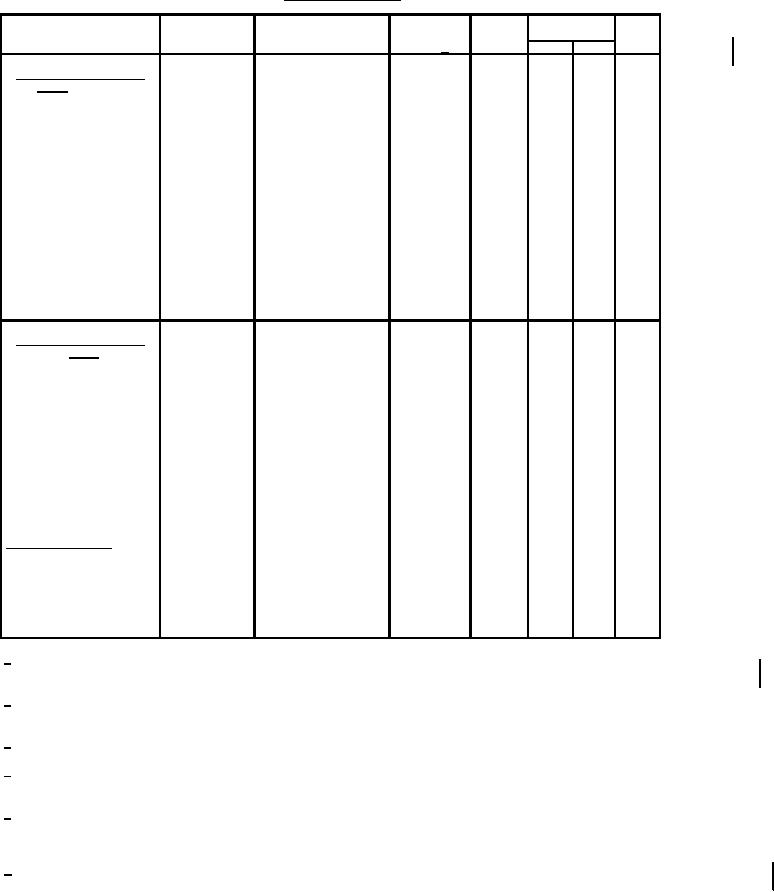
TABLE I. Testing and inspection - Continued.
Inspection
Method
Conditions
Acceptance
Symbol
Limits
Unit
MIL-STD-1311
Level 6/
Min
Max
Conformance inspection,
part 2 - Continued
Line width A
5226
---
W idth
---
0.50
mm
Ib = 200 µA dc
(magnetic deflection)
Line width C
5226
---
W idth
---
0.75
mm
Ib = 200 µA dc
(magnetic deflection)
Focusing ampere turns
5246
---
---
337
459
---
Ib = 200 µA dc;
D = 4.125 inch
Heater-cathode leakage
5251
---
---
---
---
---
current
Grid No. 2 leakage current
5251
---
---
---
---
---
Base pin solder depth
1111
---
---
---
---
---
Conformance inspection,
part 3
Life-test provisions
---
---
---
---
---
---
Group C;
t = 500 hours (min);
Eb2 = 13.200 V dc;
Ec2 = 770 V dc;
Ib = 60 µA dc
Life-test end points
---
Line width A:
---
W idth
---
0.50
mm
Ib = 200 µA dc
mm
---
W idth
---
0.75
Line width C:
Ib = 200 µA dc
V dc
---
---
38
ĆEc1
Modulation:
Ib = 200 µA dc
Periodic-check tests
Direct-interelectrode
1331
k to all
---
Ck
---
10
pF
capacitance
g1 to all
---
Cg1
---
11
pF
g2 to all
---
Cg2
---
12
pF
Cathode illumination
5216
---
---
---
---
---
1/ W hen Ec2 is greater than 330 V dc. Rg1 shall not exceed 0.5 MegΩ. W hen Ec2 is less than 330 V dc. Rg1 shall not exceed 1.5
MegΩ.
2/ W hen Ec2 is greater than 330 V dc or Ec1 is near zero, the effective resistance of the anode and grid No. 3 supply should be
adequate to limit the anode and grid No. 3 input power to 6 watts. Peak grid No. 1 drive from cutoff should never exceed 65 volts.
3/ This test to be performed at the conclusion of the holding period.
4/ Screen brightness I shall be measured as specified in MIL-STD-1311 method 5221 except that no pulsing shall be used on the grid
and the screen current shall be 26.7 µA with an anode voltage of 9 kV. The steady-state output shall be 735 cb minimum.
5/ The distance between the center of the unfocused, undeflected spot at low intensity (Ec1 near cut-off) and the center of the image
of the masking aperture observed at high intensity of the unfocused, undeflected spot shall not exceed the limit specified. Ec1
should not be held at zero for more than approximately 30 seconds to prevent damage to the screen.
6/ This specification sheet uses accept on zero defect sampling in accordance with MIL-PRF-1, table III.
3
For Parts Inquires call Parts Hangar, Inc (727) 493-0744
© Copyright 2015 Integrated Publishing, Inc.
A Service Disabled Veteran Owned Small Business