MIL-PRF-1/1203K
Dimensions
Ltr
Inches
Millimeters
Min
Max
Min
Max
Conformance inspection, part 1
(see note 5)
A
.268
.292
6.81
7.42
B
.476
.484
12.09
12.29
C
.156
.174
3.96
4.42
D
---
.335
---
8.51
E
.281
.289
7.14
7.34
F
.271
.279
6.88
7.09
G
.094
.104
2.39
2.64
H
.095
.105
2.41
2.67
J
.034
.046
0.86
1.17
K
.047
.063
1.19
1.60
L
.024
.030
0.61
0.76
M
.055
.081
1.40
2.06
N
.030
---
0.76
---
P
.086
.094
2.18
2.39
R
.022
.028
0.56
0.71
S
.430
.460
10.92
11.68
NOTES:
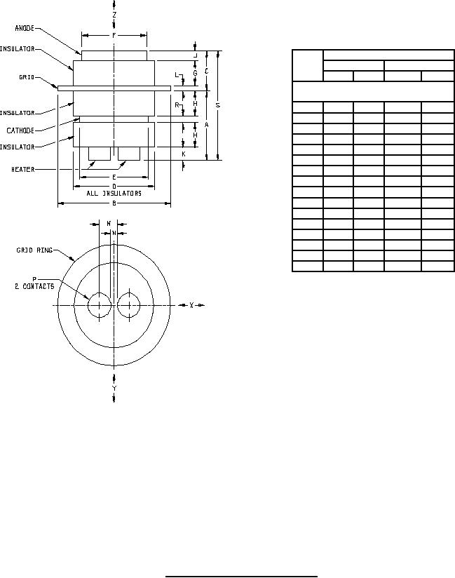
1. Eccentricity of anode, grid, and cathode with respect to centerline shall be .005 inch (0.13 mm) maximum.
2. Eccentricity of insulators with respect to centerline shall be .010 inch (0.25 mm) maximum.
3. Centerline of grid shall be reference line for horizontal tolerances.
4. Bottom surface of grid shall be reference plane for vertical tolerances.
5. The acceptance level for dimensions listed under conformance inspection, part 1, shall be 1.0. Acceptance shall be based upon
accept on zero (c = 0) sampling plan in accordance with Table III of MIL-PRF-1.
FIGURE 1. Outline drawing of electron tube type 7077.
7
For Parts Inquires call Parts Hangar, Inc (727) 493-0744
© Copyright 2015 Integrated Publishing, Inc.
A Service Disabled Veteran Owned Small Business