MIL-PRF-1/1159E
Pin connections
Pin
Element
no.
1
Filament
2
Filament center tap
3
Filament
4
No connection
Cap
Anode
Dimensions (see note 1)
Inches
Millimeters
Ltr
Min
Max
Min
Max
Conformance inspection, part 2
A
4.813
5.062
122.25 128.57
B
---
2.313
---
58.75
C
4.300
4.703
109.22 119.46
Conformance inspection, part 3
(periodic check)
D
.015
.094
0.38
2.39
E
---
.125
---
3.18
F
Base: A4-52 (see note 3)
G
.055
.060
1.40
1.52
H
.305
.445
7.75
11.30
J
.368
.382
9.35
9.70
K
.375
---
9.53
---
NOTES:
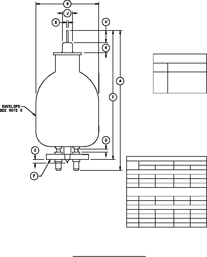
1. Metric equivalents (to the nearest .01 mm) are given for general information only and are based on 1 inch = 25.4 mm.
2. Allowable eccentricity of envelope with respect to centerline through base shall be .126 (3.20 mm) maximum.
Conformance inspection, part 3 (periodic check) shall apply.
3. For pin alignment, use gauge GA4-6.
FIGURE 1. Outline drawing of electron tube type 705WA.
2
For Parts Inquires call Parts Hangar, Inc (727) 493-0744
© Copyright 2015 Integrated Publishing, Inc.
A Service Disabled Veteran Owned Small Business