MIL-PRF-1/1112H
TABLE I. Testing and inspection - Continued.
7/
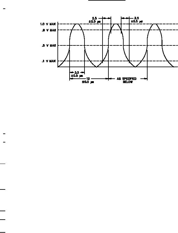
The eg pulse shall be of such shape as to provide rf output voltages which conform to the following diagram:
a.
The eg pulses shall be composed of pairs spaced 12.0 ±0.5 microseconds between centers. The repetition rate shall be
3,600 ± 90 pairs per second.
b.
The tube shall not oscillate with the input line disconnected and the input and output resonators tuned to the same
frequency provided that the middle resonator is detuned by one turn of one tuning nut from resonance.
c.
The output of the grid modulator can be loaded with a shunt impedance, if necessary, to obtain the proper waveform to
drive the TUT grid.
8/
The TUT shall deliver the rated power specified herein into a transformer adjusted load which has a VSWR of 1.5:1, or less.
9/
The TUT nor its output coupling shall be damaged if the TUT output connector is open, short circuited, or terminated in any
resistance or reactance or combination thereof between the limits of open and short circuit when the TUT is tuned in
equipment in accordance with instructions supplied by the tube supplier.
10/
A tuning curve shall be supplied with each tube. The frequency of each resonator can be set approximately by adjusting the
tuning ring spacing of each resonator according to the tuning charts. Tuning rings shall be parallel with one turn of a tuning
nut after final adjustment. When adjusted to any operating frequency in the range from F1 to F3 in accordance with the
individual cold tuning charts, and when supplied with rf drive over the range of nominal frequency ±0.5 MHz, the tube will
deliver a minimum rf output power of 30 watts into a 50-ohm resistive load.
11/
The rf drive shall be applied to the input resonator of the TUT. The rf drive may be either pulsed or cw. When a rectangular
pulse drive is used, synchronization shall be provided to allow the control-grid pulse to appear in time phase with rf pulse.
The rf drive pulse shall be free from frequency modulation which would prevent testing the tubes to the performance limits
indicated.
12/ This test shall be performed at the conclusion of the holding period.
13/
With the TUT operating, the filament voltage shall be decreased from 4.5 to 3.8 volts. The percentage change in anode
current shall be within the limits specified herein.
14/
After account has been taken of existing differences in the amplitude of adjoining eg pulses, and correction made for the 5:4
power relationship between the output voltage pulse amplitude and droop in Eb, there shall be in addition not more than 2
percent difference between the maximum amplitude pulse and the minimum amplitude pulse in a group of 24 successive
pulses. These 24 pulses may be evenly spaced in a total interval not exceeding 330 microseconds. One tube per month
shall be tested with no failures per lot.
15/
With the TUT operating under specified test conditions, removal of the grid pulse potential shall reduce the radiated rf and the
transmitted output to the maximum specified. In the absence of beam current and for any condition of tuning, the maximum
level of radiated rf or the transmitted output is specified with respect to the rf drive power.
4
For Parts Inquires call Parts Hangar, Inc (727) 493-0744
© Copyright 2015 Integrated Publishing, Inc.
A Service Disabled Veteran Owned Small Business