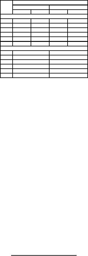
MIL-PRF-1/1049H
Dimensions
Ltr
Inches
Millimeters
Min
Max
Min
Max
Conformance inspection, part 2
A
2.875
2.975
73.03
75.57
B
1.855
1.905
47.13
48.39
C
2.650
2.768
67.31
70.31
F
.068
.128
1.73
3.25
G
.090
.150
2.29
3.81
L
1.680
1.694
42.67
43.03
Reference dimensions (see note 1)
D
1.796 MAX
45.62 MAX
E
.900 design center
22.86 design center
H
.400 design center
10.16 design center
J
.120 design center
3.05 design center
M
.860
21.84
N
1.000
25.40
NOTE:
1. These dimensions are for information only and are not required for inspection purposes.
2. Faceplate dimensions (see note 13).
Radius of curvature (inside and outside) shall be 2.33 inches (59.2 mm) minimum and 2.43 inches (61.7 mm).
Thickness at center shall be .061 inch (1.55 mm) minimum and .069 inch (1.75 mm) maximum.
Variation in edge thickness shall be .004 inch (0.10 mm) maximum.
3. Image screen dimensions (see note 13).
Thickness at center shall be .095 inch (2.41 mm) minimum and .105 inch (2.67 mm) maximum.
Variation in edge thickness shall be .010 inch (0.25 mm) maximum.
4. Refractive index for faceplate and image screen glass shall be 1.49 ± .04 inch (37.8 ± 1.0 mm).
5. No part of that portion of the tube included between metal contact ring shall protrude beyond dimension B.
6. Tube axis is established by centerline through dimension L.
7. The following ratio shall govern dimensions A, C, F, and G: A minimum ≤ C + F + G ≤ A maximum.
8. All exposed metal parts shall be nickel plated.
9. Dimension J measures depth to bearing surface of metal shoulder.
10. Minimum useful image screen diameter.
11. Minimum useful cathode diameter.
12. Depth to outside surface of image screen window.
13. Faceplate and image screen dimensions are for guidance on component parts.
Conformance check of these dimensions shall be made prior to tube assembly.
14. No glass or other protuberance permitted inside minimum diameter R, protuberance beyond this diameter
shall not exceed .031 inch (0.79 mm) deviation from flatness of external surface of image screen within
a minimum diameter of 1.260 inch (32.00 mm) shall not exceed .002 inch (0.05 mm) from peak to valley.
15. Dimension G applies over 1.260 inch (32.00 mm) diameter only.
FIGURE 1. Outline drawing of electron tube type 6914 - Continued.
8
For Parts Inquires call Parts Hangar, Inc (727) 493-0744
© Copyright 2015 Integrated Publishing, Inc.
A Service Disabled Veteran Owned Small Business