MIL-PRF-1/982D
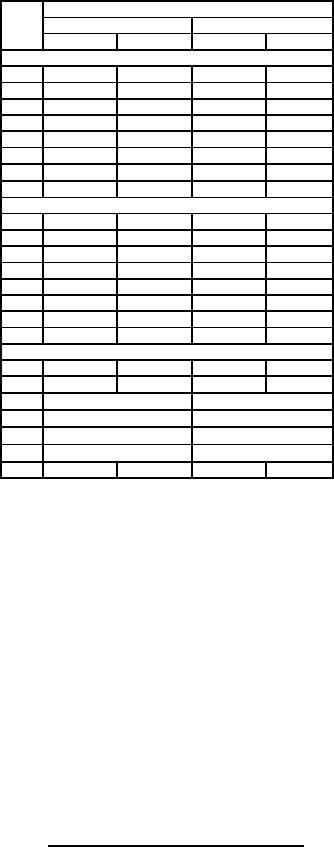
Dimensions
Ltr
Inches
Millimeters
Min
Max
Min
Max
Conformance inspection, part 1
H
1.312
1.438
33.32
36.53
J
.330
.400
8.38
10.16
K
.135
.145
3.43
3.68
L
.910
.930
23.11
23.62
M
1.203
1.234
30.56
31.34
P
.656
.719
16.66
18.26
154°30'
160°30'
154°30'
160°30'
Z
AD
1.168
1.188
29.67
30.18
Conformance inspection, part 2
A
---
1.609
---
40.87
B
---
.859
---
21.82
F
1.000
1.016
25.40
25.81
G
---
3.562
---
90.47
N
.182
.192
4.62
4.88
R
.203
.234
5.16
5.94
S
.484
.516
12.29
13.11
U
---
.116
---
2.95
Qualification inspection
C
.767
.797
19.48
20.24
T
.766
.797
19.46
20.24
70°
V
---
70°
W
---
70°
X
---
70°
Y
---
AB
1.271
1.312
32.28
33.32
NOTES:
1. The tuning screw shall be lubricated with Oildag or equal non-corrosive lubricant. It shall be capable of being
operated smoothly through its entire range without perceptible binding.
2. The base shall be capable of being inserted in a gauge 1.219 (30.96 mm) thick having 4 holes .250 (6.35 mm)
deep from the top of the gauge whose diameters are .103 (2.62 mm) for the contact pins. Remaining portion of
hole to be clearance, approximately .016 (0.41 mm) larger in diameter and a fifth hole whose diameter .160
(4.06 mm) by 1.219 (30.96 mm) deep for the output lead. All holes located on the true center. Also a center
hole having the contour of the pilot but with the clearance of .002 (0.05 mm) over the maximum diameter.
3. Nickel (30 msi silver permissible).
4. Dimensions are in inches.
5. Metric equivalents are given for general information only.
FIGURE 1. Outline drawing of electron tube type 2K25 - Continued.
5
For Parts Inquires call Parts Hangar, Inc (727) 493-0744
© Copyright 2015 Integrated Publishing, Inc.
A Service Disabled Veteran Owned Small Business