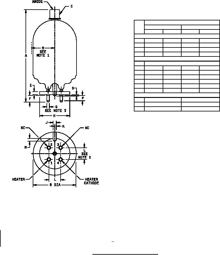
MIL-PRF-1/911E
Dimensions
Ltr
Inches
Millimeters
Min
Max
Min
Max
Conformance inspection, part 2
A
5.625
5.875
142.88
149.23
B
---
2.563
---
65.10
H
1.787
1.813
45.39
46.05
S
---
.125
---
3.18
Conformance inspection, part 3 (see note 4)
C
Cap: C1-5 (EIA)
G
.183
.191
4.65
4.85
J
.171
.203
4.34
5.16
K
.078
.110
1.98
2.79
M
.171
.203
4.34
5.16
P
.328
---
8.33
---
R
---
1.406
---
35.71
Reference dimensions
E
.188
4.78
F
.406
10.31
L
.688
17.48
NOTES:
1. Eccentricity with respect to centerline of base.
2. The base shall be capable of entering a gauge .25 inch (6.4 mm) thick having 4 holes of .214 inch (5.44 mm)
diameter located on .69 inch (17.5 mm) centers.
3. Solder should not extend laterally beyond cylindrical surface of studs.
4. Dimensions shall be checked during the initial production and once each succeeding 12-calendar months in which
there is production. An accept on zero defect sampling plan shall be used, with sample of three tubes with an
acceptance number of zero. In the event of failure, the test will be made as a part of conformance inspection,
part 2, with an acceptance level of 6.5 (see 7/). The "12-calendar month" sampling plan shall be reinstated after
three consecutive samples have been accepted.
FIGURE 1. Outline drawing of electron tube type 719A.
4
For Parts Inquires call Parts Hangar, Inc (727) 493-0744
© Copyright 2015 Integrated Publishing, Inc.
A Service Disabled Veteran Owned Small Business