MIL-PRF-1/889J
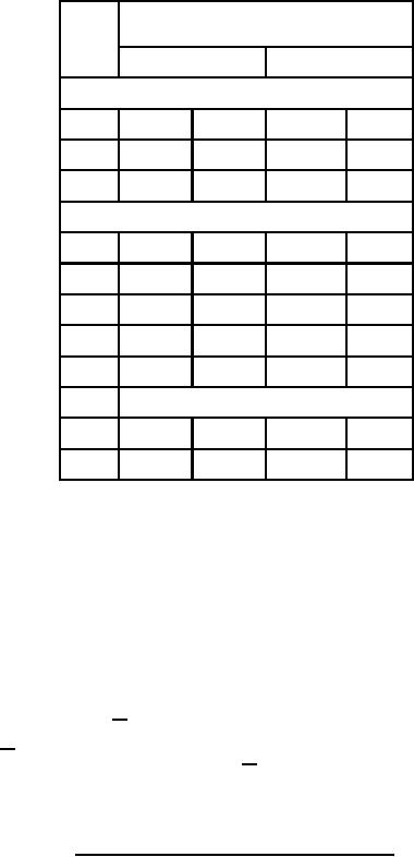
Dimensions
LTR
Millimeters
Inches
Conformance inspection, part 2
Min
Max
Min
Max
A
59.03
62.59
2.324
2.464
C
45.97
48.51
1.810
1.910
Conformance inspection, part 3
B
40.89
41.66
1.610
1.640
D
19.05
20.57
.750
.810
E
18.03
20.07
.710
.790
F
35.71
1.406
G
4.75
.187
H
Base: B8-236 (see note 1)
J
14.20
14.55
.559
.573
K
6.10
.240
NOTES:
1. Pin alignment shall be checked by means of gage GB8-3. Dimensions of control-grid contact shall be inspected by means of
gages specified on Drawing 246-JAN 13/ and shall be inspected during conformance inspection, part 2.
2. Alignment of anode, screen-grid, and control-grid contact surfaces shall be determined by means of a gage specified on
Drawing 168-JAN 13/. Conformance inspection, part 2, shall apply.
3. Air-system socket shall be as specified on Drawing 246-JAN 13/, EIMAC SK-600, or equivalent.
4. Location of guide lug of control-grid contact shall be referenced by a notch or arrow on the anode radiator in position shown.
5. Anode clamping shall be confined to anode radiator.
6. Top cap outline optional provided it meets requirements of dimensions J and K.
FIGURE 1. Outline drawing of electron tube types 7203 and 7203A - Continued.
7
For Parts Inquires call Parts Hangar, Inc (727) 493-0744
© Copyright 2015 Integrated Publishing, Inc.
A Service Disabled Veteran Owned Small Business