MIL-PRF-1/884G
Pin connections
Pin No.
Element
f1
1
f1
2
f2
3
f2
4
a
top lead
g
cap
Dimensions
Ltr
Inches
Millimeters
Min
Max
Min
Max
Conformance inspection, part 2
A
7.250
7.625
184.15
193.68
B
---
3.563
---
90.50
C
6.500
6.875
165.10
174.63
D
5.313
5.688
134.95
144.48
E
.438
---
11.13
---
H
1.688
1.813
42.88
46.05
Conformance inspection, part 3 (see note 3)
F
.120
.126
3.05
3.20
K
Cap: C1-23 (EIA)
L
Base: A4-62 (EIA)
M
---
.187
---
4.75
Reference dimensions
G
60°
60°
J
.031 x 45° or .005R
0.79 x 45° or 0.13 R
NOTES:
1. Heat radiating connectors HR-6 (grid) and HR-7 (anode) or equivalent, are recommended for all applications.
2. Dimension A includes .060 inch (1.52 mm) solder tolerance on length of pins.
3. These dimensions shall be checked annually with the following accept on zero defect sampling plan:
n1 = 4
c1 = 0
In case of failure after sampling, the failing dimension(s) shall become conformance inspection, part 2, for
three consecutive successful submissions, at which time the test may revert to the conformance inspection,
part 3 basis.
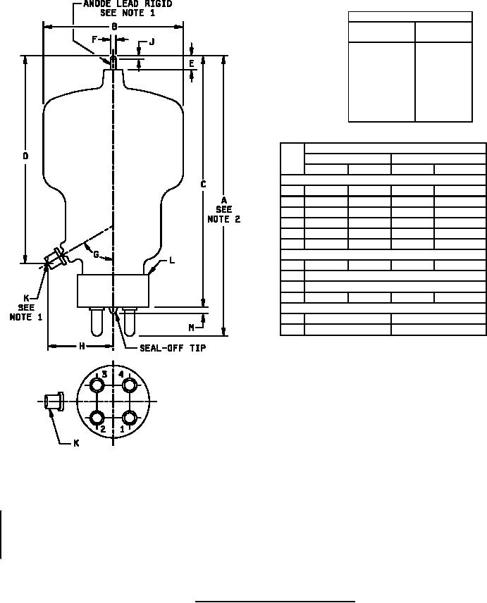
FIGURE 1. Outline drawing of electron tube type 304TH.
4
For Parts Inquires call Parts Hangar, Inc (727) 493-0744
© Copyright 2015 Integrated Publishing, Inc.
A Service Disabled Veteran Owned Small Business