MIL-PRF-1/597F
Test method.
Mask tube with light-proof material. The light-source should be located so that light from it is striking the cathode
of the photomultiplier. (Light from the light source should be the only light striking the cathode.) The opening of
the iris is varied to obtain approximately 10 microamperes of anode current. Observe the tube noise signal as
displayed by the oscilloscope. Reduce pressure of vacuum chamber to 130 millimeters of mercury. The tube
should be subjected to this pressure for a period of 2 minutes. During pressure reduction, the tube noise signal,
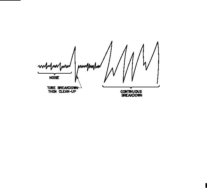
as displayed by the oscilloscope, should be observed to determine tube breakdown. When breakdown occurs,
the signal being monitored by the oscilloscope will resemble the following:
When continuous breakdown occurs, a change in anode current will result.
13. Vary light to obtain approximately 10 microamperes of anode current.
14. The tube shall operate without indication of breakdown in an evacuated chamber in which the pressure does not
exceed 130 mmHg absolute.
15. With 10 lumen incident on the cathode, vary the overall voltage (Ebb) to obtain an anode current of 200 A dc.
-5
Exclude light and read the dark current.
16. The clamp shall be as specified in Drawing 216-JAN.
17. After the socket test is performed, the tube shall meet the requirements of all the tests specified in conformance
inspection, part 1.
18. All conformance inspection, part 1, tests to be performed at the conclusion of the holding period.
19. An ac supply voltage may be used having a peak value equal to this maximum value.
20. This specification sheet uses accept on zero defect sampling in accordance with MIL-PRF-1, table III.
4
For Parts Inquires call Parts Hangar, Inc (727) 493-0744
© Copyright 2015 Integrated Publishing, Inc.
A Service Disabled Veteran Owned Small Business