MIL-PRF-1/374F
NOTES:
1. The tube shall be suspended by a yoke clamped to the cavity center conductor centered at a point 2.375 (60.33 mm)
inches from the end of the center conductor. The weight of the yoke shall be 0.25 pound (113.4 g) and the portion of the
yoke against which the hammer strikes shall have a spherical radius 1 (25.4 mm) inch.
2. The tube shall be within the limits of all power output tests after vibration.
3. A 25,000-ohm resistor shall be placed in series with the repeller lead and 4,000 peak ac volts shall be applied between
the cavity center conductor and the repeller lead. No breakdown as indicated on a high-resistance ac voltmeter in
parallel with the tube shall occur.
4. Each tube shall be tested to assure satisfactory operation under the following conditions:
Cavity I, II, and III, in accordance with Drawing 181-JAN.
The power output shall maximize between the specified repeller voltage limits and shall be above the limits specified.
The tube shall deliver power over a repeller voltage range of 10 V. The tube shall be assumed satisfactory without a
test at 10 V from a maximum power repeller voltage between -30 V and 0 V.
5. A 15-MegΩ resistor shall be placed in series with the repeller lead.
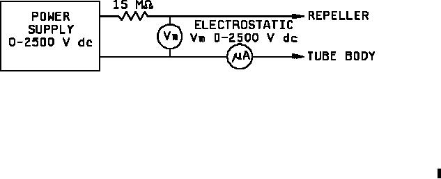
6. Apply 2,000 V dc through a 15-MegΩ protective resistor in series with a 50 A full scale meter shunted by a
momentary push button switch, as shown in circuit diagram below.
Current shall be read with tube at standard atmospheric pressure. The same measurement shall then be made at a
pressure of 81.28 mm of mercury, care being taken not to depress the shorting button across the microammeter if any
initial deflection exists. The increase in current shall not exceed 5 A over that read at atmospheric pressure, 1 minute
after application of full voltage.
7. Power output (1), test cavity I, limits shall be used.
8. This specification sheet uses accept on zero defect sampling in accordance with MIL-PRF-1, table III.
3