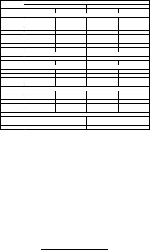
MIL-PRF-1/1767D
Dimensions
LTR
Millimeters
Inches
Minimum
Maximum
Minimum
Maximum
Conformance inspection, part 2
C
15.24
19.30
.600
.760
D
48.16
49.17
1.896
1.936
E
79.58
80.59
3.133
3.173
F
96.32
97.33
3.792
3.832
G
101.09
102.11
3.980
4.020
H
4.78
---
.188
---
J
4.78
---
.188
---
K
4.78
---
.188
---
L
43.05 BASIC (See note 5)
1.695 BASIC (See note 5)
O
9.02 BASIC (See note 5)
.355 BASIC (See note 5)
P
228.60
238.12
9.000
9.375
R
23.37 BASIC (See note 5)
.920 BASIC (See note 5)
T
9.52
----
.375
---
U
111.91
113.49
4.406
4.468
V
94.44
96.04
3.718
3.781
W
5.56
---
.219
---
Conformance inspection, part 3 (See note 3)
A
189.48
192.53
7.460
7.580
B
21.72
22.73
.855
.895
M
115.57
121.49
4.550
4.783
N
61.26
70.82
2.412
2.788
S
90.42
93.57
3.560
3.684
Reference dimensions (See notes 6 and 7)
X
6.60
.260
Y
20.98
.826
Z
40.64
1.600
NOTES:
1. The total indicator reading (T.I.R.) (the sum of the positive and negative deflection shown by the indicator when measuring
the eccentricity of the surface with respect to another, with the reference axis established) of the screen grid and filament
contact surfaces shall not exceed .040 (1.02 mm) with respect to the control grid and anode contact surfaces when the
latter surfaces are rotated on rollers at the points indicated by the arrows. Conformance inspection part 2, shall
apply.
2. Top cap outline optional provided it meets requirements of dimensions B and T.
3. Dimensions shall be checked every 6 months, with eight samples and acceptance upon zero defects.
Separate samples may be used at the option of the manufacturer. None of the listed tests shall be considered destructive
except in case of failure. In the event of failure after sampling, that specific test shall become conformance inspection, part
2; after three consecutive successful submissions, the testing may revert to the conformance inspection, part 3 tests.
4. The T.I.R. of the screen grid and filament contact surfaces shall not exceed .040 (1.02 mm) with respect to the control gird
and anode contact surface when the latter surfaces are rotated on rollers at the points indicated by the arrows.
5. Basic dimensions is s numerical value used to describe the theoretically exact size, shape or location of a feature or datum
target. It is the basis from which permissible variations are established by tolerances on other dimensions, in notes or by
feature control symbols.
FIGURE 1. Outline drawing of electron tubes type 8281 - Continued.
5
For Parts Inquires call Parts Hangar, Inc (727) 493-0744
© Copyright 2015 Integrated Publishing, Inc.
A Service Disabled Veteran Owned Small Business