MIL-PRF-1/1679C
Dimensions
Ltr
Inches
Millimeters
Min
Max
Min
Max
Conformance inspection, part 2
A
5.750 6.000 146.05
152.40
B
----
3.063
----
77.80
E
2.885 2.905
73.28
73.79
P
.043
.057
1.09
1.45
V
1.788 1.813
45.42
46.05
Conformance inspection, part 3 (see 12/)
C
5.344 5.594 135.74
142.09
D
1.125 1.250
28.58
31.75
F
.328
---
8.33
---
G
.438
.500
11.13
12.70
H
.016
---
0.41
---
J
Cap: C1-41
K
.050
---
1.27
---
L
.150
---
3.81
---
M
---
.075
---
1.91
N
.250
---
6.35
---
S
.340
---
8.64
---
T
.171
.203
4.34
5.16
U
.171
.203
4.34
5.16
W
.183
.191
4.65
4.85
X
.157
---
3.99
---
Reference dimensions (see note 2)
Pin connectors
Pin No.
Element
Q
---
.188
---
4.78
1
h
R
---
.687
---
17.45
2
g2
Y
---
.031
---
0.79
3
g1
RAD
RAD
4
hk
Cap
a
NOTES
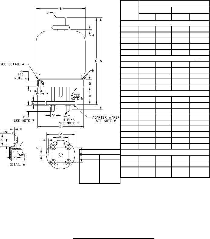
1. There shall be an electrical tie between pin 4 and clamping flange.
2. Dimensions without tolerances are for information and are not required for inspection purposes.
3. Pins shall enter gauge .250 inch (6.35 mm) thick, with four holes .214 inch (5.44 mm) diameter
located on .687 inch (17.45 mm) centers and with center hole .250 inch (6.35 mm) diameter.
4. Defines cylindrical surface available for clamping which must not be deformed by action of clamps.
5. The adapter wafer will not be removed.
6. Dimensions optional where not specified.
7. Defines length available for contact.
8. Tube base envelope material shall be approved type ceramic.
FIGURE 1. Outline drawing of electron tube type 8252W.
6
For Parts Inquires call Parts Hangar, Inc (727) 493-0744
© Copyright 2015 Integrated Publishing, Inc.
A Service Disabled Veteran Owned Small Business