MIL-PRF-1/1636C
TABLE I. Testing and inspection - Continued.
13/ This test shall be performed simultaneously with the operation (1) test. An anode delay time measurement
shall be made at the end of 2 and 10 minutes of the operation (1) test. The change in anode delay time (with
respect to the 2-minute reading) shall not exceed the specified value at any time during this test.
14/ The tube shall be tested by applying a peak forward anode voltage not to exceed that specified in the test
conditions for the time jitter test immediately after the cathode warmup period (tk). The variation in firing
time (tj) shall not be greater than the amount specified after 60 seconds of operation.
15/ This test shall be conducted for a total of 5 consecutive hours with no more than 3 kickouts and with no
evidence of detrimental anode heating. The tube shall be started with Eres 107.5 percent V ac and operate at
this value for 4 hours. At the start of the fifth hour, and while the tube is still operating, the filament voltage
shall be lowered to Eres = 92.5 percent V ac and remain there for the final hour of operation.
16/ This specification sheet uses accept on zero defect sampling plan in accordance with MIL-PRF-1, table III.
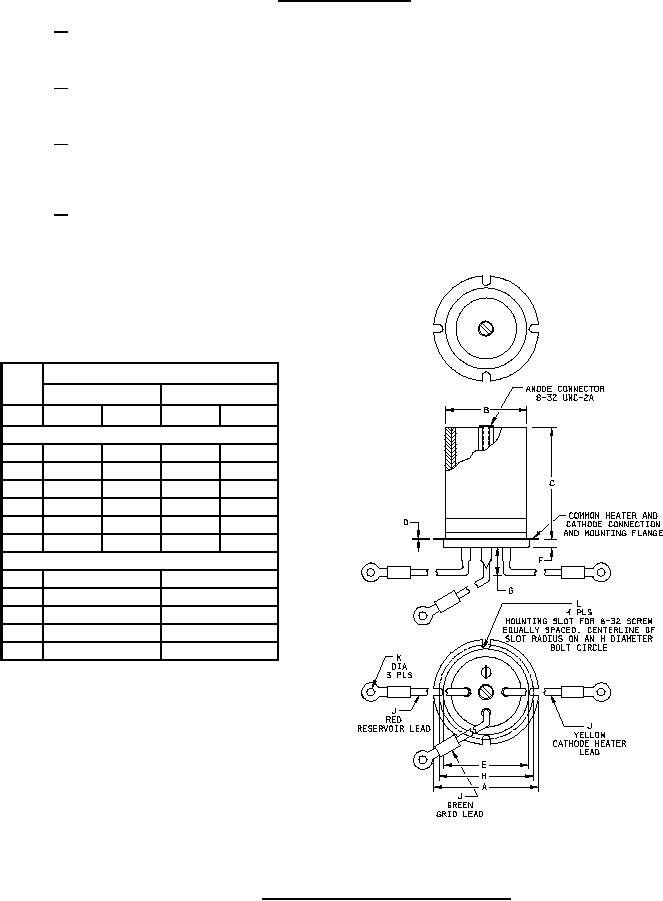
Dimensions
Ltr
Inches
Millimeters
Min
Max
Min
Max
Conformance inspection, part 2
A
1.870
1.880
47.50
47.75
B
1.365
1.385
34.67
35.18
C
1.875
2.000
47.62
50.80
E
1.421
1.453
36.09
36.91
F
0.156
0.280
3.96
7.11
G
----
1.000
----
25.40
Reference dimensions
D
0.030
0.76
H
1.656
42.06
J
6.000
152.40
K
0.203
5.16
L
0.150
3.81
FIGURE 1. Outline drawing of electron tube type 7782.
4