MIL-PRF-1/1618C
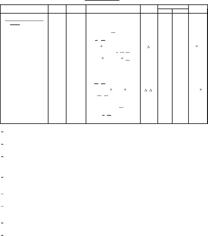
TABLE I. Testing and inspection - Continued.
Limits
Inspection
Method
Test
Conditions
Symbol
Min
Max
Unit
Conformance inspection,
part 3 - Continued
High frequency vibration
1031
No voltages
12/
---
---
---
---
Shock
1041
8/ 12/
---
---
---
---
Air cooling
1143
2
---
TA+50
TA = 50 C (max)
T
C
Pi - Po = 150 W 9/ 12/ 14/
Tuner operating torque
4223
Torque
---
32
inch-
TA = -55 C and +125
12/
ounce
Anode-cathode cap
---
C
4.0
8.0
pF
capacitance
Mechanical fatigue
4223
10/ 12/
N
2,500
---
cycles
Temperature coefficient
4027
4
---
0.25
T(anode) = 70 C to 100 C
F/ T
MHz/ C
12/ 14/
Barometric pressure
1002
Pressure = 349 mmHg
---
---
----
---
reduced
F = 9,160 MHz
12/
Low temperature
1047
4
Stability 7/ 12/
MP
---
2
%
operation
1/
Unless otherwise specified, the acceptance level for all tests listed under conformance inspection, part 1, shall be 1.0 percent with
inspection level of II.
2/
Unless otherwise specified, the acceptance level for all tests listed under conformance inspection, part 2, shall be 6.5 percent with
inspection level of S3.
3/
The magnetron may be coupled directly to a RG-51/U waveguide in accordance with MIL-W-85, with a UG-52B/U chock flange in
accordance with MIL-PRF-3922/25. However, for a minimum VSWR of this coupling, it is recommended that a specially designed
choke flange be used which mates with the angular RG-51/U output of the magnetron to provide a straight section of RG-51/U
waveguide through the coupling network.
4/
Immediately after the holding period, and after a 120-second preheat, the pulse voltage as specified in conformance inspection, part
1, shall be instantaneously applied and the magnetron missing pulse count shall not exceed 1 percent over the first minute of
operation.
5/
The RF bandwidth shall be within the limits specified when a VSWR of 1.5 is introduced in the load at a distance no greater than
0.197 inches (0.5 meters) from the magnetron coupling flange, the phase being adjusted for the worst spectrum.
6/
When the direction of tuner drive is reversed at the frequency specified, the magnetron shall not continue to tune in the original
direction by more than the specified frequency increment before reversing. Test to be performed at 9,000 MHz, and 9,080 MHz,
and 9,160 MHz.
7/
Stability shall be measured with the VSWR adjusted to the phase which produces maximum instability. The missing pulses shall be
counted during any 3 minute period of a test interval not to exceed 6 minutes.
8/
The tube shall be subjected to five shocks of peak amplitude duration in accordance with MIL-STD-202, method 213, test condition
G. Following the shock test, the tube shall show no mechanical damage, and shall pass the power output and pulse voltage
requirements of conformance inspection, part 1.
3
For Parts Inquires call Parts Hangar, Inc (727) 493-0744
© Copyright 2015 Integrated Publishing, Inc.
A Service Disabled Veteran Owned Small Business