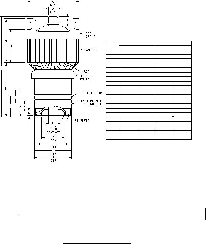
MIL-PRF-1/1427G
Dimensions
Ltr
Inches
Millimeters
Min
Max
Min
Max
Conformance inspection, part 2
C
.600
.760
15.24
19.30
D
1.896
1.936
48.16
49.17
E
3.133
3.173
79.58
80.59
F
3.792
3.832
96.32
97.33
G
3.980
4.020
101.09
102.11
H
.188
---
4.78
---
J
.188
---
4.78
---
K
.188
---
4.78
---
L
1.764
1.826
44.81
46.38
P
8.625
9.125
219.08
231.78
R
.986
1.050
25.04
26.67
T
.375
---
9.53
---
Conformance inspection, part 3 3/
A
4.812
4.938
122.22
125.43
B
.855
.895
21.72
22.73
M
4.188
4.563
106.38
115.90
N
2.875
3.250
73.03
82.55
S
3.875
4.250
98.43
107.95
NOTES:
1. The total indicator reading (the sum of the positive and negative deflection shown by the indicator when measuring the
eccentricity of one surface with respect to another, with the reference axis established) of the screen grid and filament contact
surfaces shall not exceed .040 inch (1.02 mm) with respect to the control grid and anode contact surfaces when the latter
surfaces are rotated on rollers at the points indicated by the arrows. (Conformance inspection, part 2).
2. Letters H, J, K, N, and T also represent contact surfaces.
3. Dimensions shall be checked yearly. An accept on zero defect sampling plan shall be used, with sample of three tubes with an
acceptance number of zero. In the event of failure, the test will be made as a part of conformance inspection, part 2, acceptance
level 6.5 (see 11/). The yearly sampling plan may be reinstated after three consecutive samples have been accepted.
FIGURE 1. Outline drawing of electron tube type 8170W .
5
For Parts Inquires call Parts Hangar, Inc (727) 493-0744
© Copyright 2015 Integrated Publishing, Inc.
A Service Disabled Veteran Owned Small Business