MIL-PRF-1/1254E
Dimensions
Ltr
Inches
Millimeters
Min
Max
Min
Max
Conformance inspection, part 1
J
.200
---
5.08
---
K
1.000
1.125
25.40
28.58
L
1.545
1.565
39.24
39.75
M
1.109
1.140
28.17
28.96
N
.920
.980
23.37
24.89
Conformance inspection, part 2
P
2.165
2.175
54.99
55.25
Q
1.276
1.284
32.40
32.61
R
.156
---
3.96
---
S
.245
.255
6.22
6.48
Qualification
A
2.560
2.590
65.02
65.79
B
1.610
1.640
40.83
41.66
C
.375
---
9.53
---
D
.546
.578
13.87
14.68
E
.234
.265
5.94
6.73
F
1.109
1.140
28.17
28.96
G
.234
.265
5.94
6.73
NOTES:
H
.140
.171
3.56
4.34
1. Metric equivalents (to the nearest 0.01 mm) are given for general
information only and are based upon 1 inch = 25.4 mm.
2. The rectangle formed by the four mounting holes on each flange shall be centered on the flange face within .031 inch
(0.79 mm).
3. Silver plate 100 MSI, or equivalent.
4. Rhodium flash over silver plate optional.
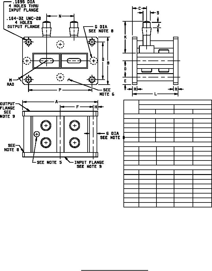
5. Exhaust tube shall not extend beyond flange and shall not block mounting holes.
6. Input flange of tube shall be flat within .004 inch (0.10 mm).
7. Finish: black paladin primer followed by optical black baking enamel, or approved equivalent, to all outside surfaces
except contacting surfaces of flanges, holes, and threads of flanges and electrode insulators and caps.
8. Four .250 inch (6.35 mm) diameter rods brazed or welded to flanges in eight places on tube flanges spaced as shown on
figure 1. Rods for mechanical support only.
9. Mark "input" or "output" on edge of each flange as appropriate.
FIGURE 1. Outline drawing of electron tube type 7381.
5
For Parts Inquires call Parts Hangar, Inc (727) 493-0744
© Copyright 2015 Integrated Publishing, Inc.
A Service Disabled Veteran Owned Small Business